Bi-Directional Motor Control
In the previous section, we learned how to work with motors. Now, we will learn how to make that motor rotate in not one, but both directions. One such way is through the use of a DPDT (double-pole double-throw) relay. This relay switches the direction of current flow through the motor, thus switching the direction it spins when it does so. *Remember to use the TIP 120 Transistor!
Below, I have constructed a circuit using the TIP 120 and a relay.

A DPDT relay controlling a Motor.
The motors spins clockwise depending on the orientation of power/ground. Reverse them, and the rotation reverses.
The H Bridge
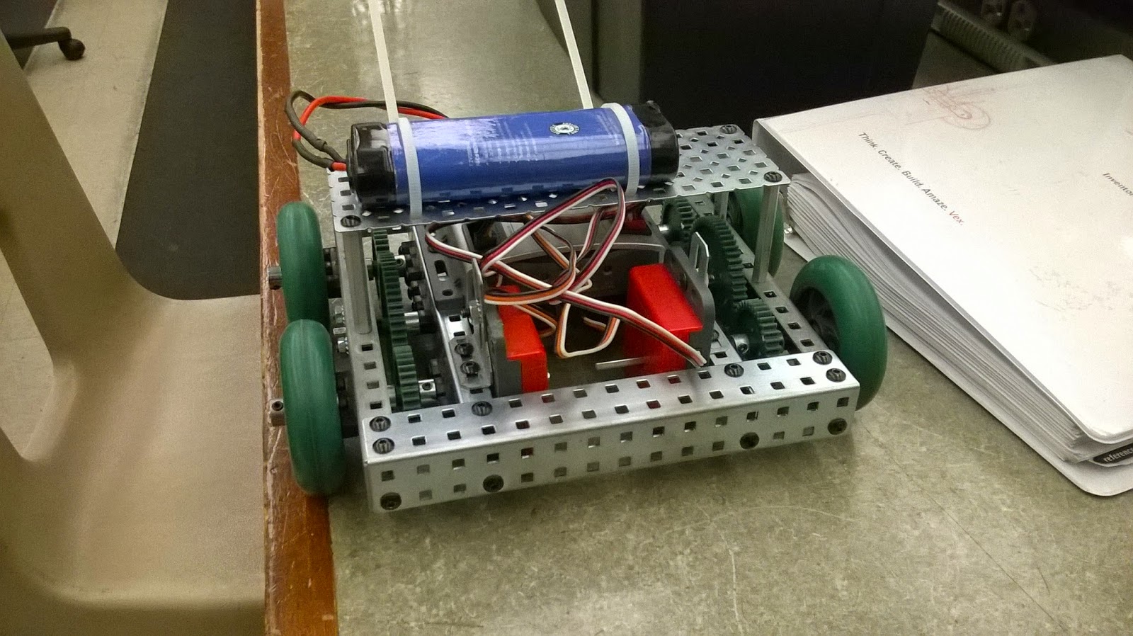
Another way to control motors is through the use of an H Bridge. It is called the H Bridge because of the way the components are oriented in an H. It has 4 switching elements: called high side left, high side right, low side left, and low side right. The H Bridge operates by switching on opposite corners of the H bridge together, with the other 2 off. So the High side left and the Low side right would turn on together, while the Hide side right and Low side left turn on together. One of those two combinations causes the motor to spin clockwise, while the other spins it counterclockwise. Do remember that the motor only runs on 1.5V (any more will cause damage to the motors). Attach the 1.5V across the top and the bottom of the H bridge, and attach the microcontroller pins 12 (to ground), and 13 (to power). If you want to reverse the direction of the pins, reverse the pins 12 and 13.
The H Bridge rotating clockwise using a 5V power supply.

 |
| An overview of the circuit. |
Now, we will use the arduino to control the motors!

 |
| Setting A High and B Low rotates it in one direction, while setting B High and A Low turns it in the other direction. Setting A and B equal makes the motor stop. |
Arduino: Input & Output Devices
Now we will learn of several Input and Output devices that we can interface with the Arduino. But first, let's introduce a new function that can be helpful to us in the future: the for statement. The for statement is used for actions that must be repeated multiple times. The for statement is as follows:
for(initialization; condition; increment)
{
//Statements
}
The initialization is the initial starting variable, while the condition is the limit to which the for statement is repeated, and the increment is the level that the variable is raised by after the loop has been run. Now, let's make an LED blink on/off with increasing frequency using this new statement!

Digital Inputs
Digital input are inputs that have 2 states: on or off. Some examples include micro switches, push switches, reed switches, and more. We will create a circuit where the Arduino will not supply power to the LED unless the switch is pressed. |
| The Circuit in its off state. |
 |
| The circuit in its on state. |
 |
| The code for the digital switch. |
Light Dependent Resistors (LDR)
Another type of input that we can use is the LDR. This resistor changes value based on the amount of light that it sees. Using this, we can use a range of values to set different reactions based off of the amount of light.
 |
| An example code for using the LDR to control 2 LEDs. |
Depending on how far my hands were, the LDR turned on a different combination of LEDs.
Thermistors
Just as there is a resistor to change value based on light, there are also resistors that change based on heat. Below is a circuit that uses the thermistor to tell the motor to turn on or off based off of how warm or cool it was.

Buzzers and Potentiometers
Similar to previous sections, the potentiometer is a variable resistor that changes value based on the rotation of the knob. We can use this to turn on the buzzer based on how much it has been turned.
 |
| The code for the buzzer. |
The potentiometer acts as an input, which then goes through the Arduino, which turns on the buzzer, the output.